Rj45 Female Pinout Diagram
RJ45 pin numbering
- Connector Pinout Standards
- Rj45 Female Connector Pin Diagram
- Rj45 Female Pinout Diagram Types
- Rj45 Connector Pin Diagram
- Rj45 Female Pinout Diagram Unlabeled
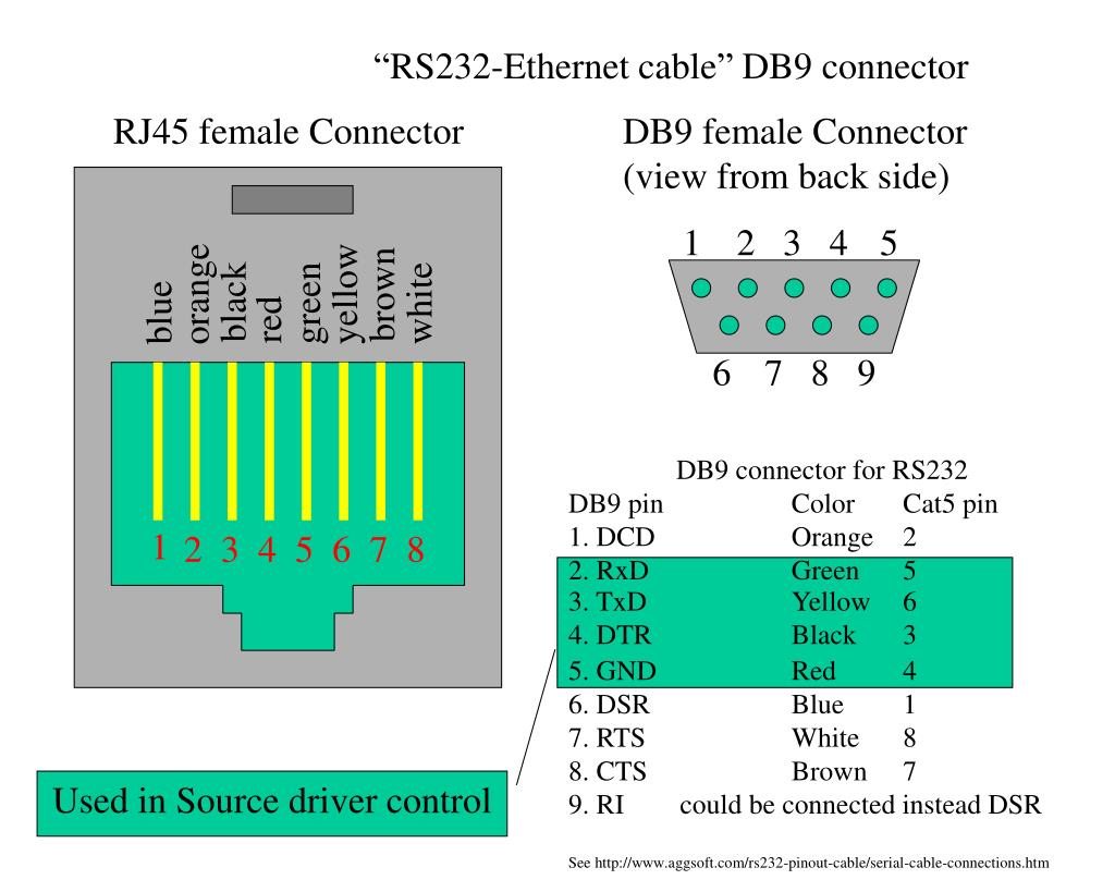
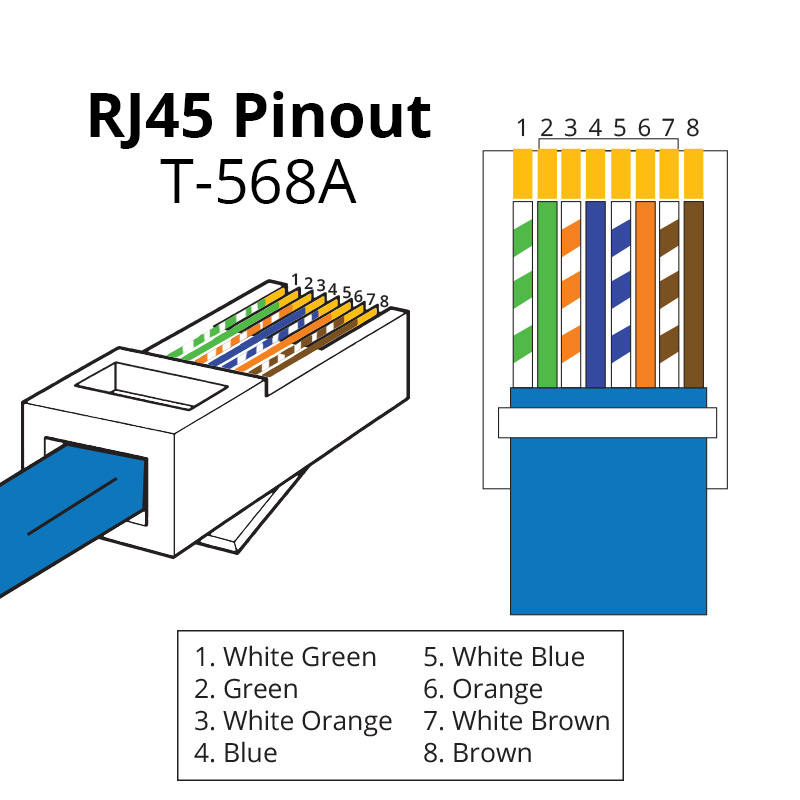
Before we start with the discussion of wiring schemes for modular jacks, it is good to know how pins are numbered on RJ45 and other modular jacks. The following scheme shows the exact pin numbering on both male and female RJ45 connectors.
To get started finding Female Rj45 Ethernet Cable Wiring Diagram Diagram Files Free Downloads, you are right to find our website which has a comprehensive collection of manuals listed. Our library is the biggest of these that have literally hundreds of thousands of different products represented. Waterproof IP68 Shielded CAT6 RJ45 Female to Female Field Installable Coupler Waterproof CAT6 Quick Release RJ45 Connectors IDC Term Block CAT6 Quick Release Case Side Shielded Waterproof RJ45 Connector, with IDC Termination Block.
All other modular jacks—like RJ11—start counting at the same side of the connector. In the wiring diagrams with modular jacks on this site we prefer to use a picture of the jack upside down, with the hook underneath.
The straight through RJ45 network cable, EIA/TIA 568B
The most common wiring for RJ45 cables is the straight through cable. In this cable layout, all pins are wired one-to-one to the other side. The pins on the RJ45 connector are assigned in pairs, and every pair carries one differential signal. Each line pair has to be twisted. If UTP or FTP cable is used, the pairs have orange, brown, blue and green colors. The wiring of these cables to RJ45 connectors to make a straight through cable is defined by EIA/TIA 568B. The RJ45 connectors on both ends are wired in the same way. The color scheme is shown below.
The cross over RJ45 network cable, EIA/TIA 568A
The straight through RJ45 cable is commonly used to connect network cards with hubs on 10Base-T and 100Base-Tx networks. On network cards, pair 1-2 is the transmitter, and pair 3-6 is the receiver. The other two pairs are not used. On hubs, switches and routers, pair 1-2 is the receiver and 3-6 the transmitter. Because of this a straight through RJ45 cable can be used to connect network cards to hubs.
In very small network configurations where only two computers have to be connected, the use of a hub is not necessary. The straight through RJ45 cable cannot be used in that situation. Also when two hubs have to be connected to increase the number of nodes on a network segment, this cable is not appropriate. In both situations a cross over RJ45 cable is necessary, where the transmit and receive lines on both RJ45 connectors are cross connected. The color coding for the cross over RJ45 cable has been defined in the EIA/TIA 568A standard.
Please note: One RJ45 connector has to be wired as EIA/TIA 568B, the other as EIA/TIA 568A. When wiring both ends as EIA/TIA 568A, the resulting cable is a straight through cable again.
Connector Pinout Standards
Common data and voice wiring schemes
Depending of the situation where modular cables are used, the wiring schemes with modular jacks differ. The most common wiring schemes can be seen in the picture below.

Assortment of usb to rj45 cable wiring diagram it is possible to download for free. Please download these usb to rj45 cable wiring diagram by using the download button, or right click on selected image, then use Save Image menu.
What is a Wiring Diagram?
A wiring diagram is a simple visual representation in the physical connections and physical layout associated with an electrical system or circuit. It shows how the electrical wires are interconnected and can also show where fixtures and components could possibly be coupled to the system.
Wiring diagrams help technicians to find out how the controls are wired to the system. Many people can see and understand schematics generally known as label or line diagrams. This type of diagram is much like having a photograph with the parts and wires all connected up.
usb to rj45 cable wiring diagram
Rj45 Female Connector Pin Diagram
Wiring Diagram Sheets Detail:
- Name: usb to rj45 cable wiring diagram – FT232 USB to serial RS232 console rollover cable for Cisco routers from China in puter Cables & Connectors from puter & fice on Aliexpress
- File Type: JPG
- Source: aliexpress.com
- Size: 123.11 KB
- Dimension: 700 x 492
Wiring Diagram Sheets Detail:
- Name: usb to rj45 cable wiring diagram – Apc USB to RJ45 Cable Pinout Rj11 cable wiring diagram Rj45 splitter wiring diagram
- File Type: JPG
- Source: pinterest.com
- Size: 12.57 KB
- Dimension: 236 x 177
Wiring Diagram Pics Detail:
- Name: usb to rj45 cable wiring diagram – usb to rj45 wiring diagram pores co rh pores co usb to rj45 cable wiring diagram
- File Type: JPG
- Source: chasingdeer.co.uk
- Size: 240.27 KB
- Dimension: 847 x 701
Wiring Diagram Pics Detail:
- Name: usb to rj45 cable wiring diagram – Moreover Rs232 to Rj45 Wiring Diagram Graphics Unique Usb to Rj45
- File Type: JPG
- Source: kanvamath.org
- Size: 114.99 KB
- Dimension: 1024 x 525
Wiring Diagram Sheets Detail:
- Name: usb to rj45 cable wiring diagram – Usb to Cat5 Wiring Diagram New 1m Usb to Down Angle Micro Usb Cable Usb 2 0 Cables
- File Type: JPG
- Source: kmestc.com
- Size: 159.16 KB
- Dimension: 1457 x 943
Wiring Diagram Pics Detail:
- Name: usb to rj45 cable wiring diagram – ponent Absolute Question And Answer Thread V 3 Ask Your Questions Here Rj45 To Usb Wiring Diagram Cablespsx Cable Need Female Pinout Connection usb to
- File Type: JPG
- Source: pinterest.ie
- Size: 148.51 KB
- Dimension: 900 x 900
What is often a Wiring Diagram?
A wiring diagram is an easy visual representation with the physical connections and physical layout of your electrical system or circuit. It shows how a electrical wires are interconnected and may also show where fixtures and components could be coupled to the system.
When and How to Use a Wiring Diagram

Use wiring diagrams to help in building or manufacturing the circuit or computer. They are also a good choice for making repairs.
Rj45 Female Pinout Diagram Types
DIY enthusiasts use wiring diagrams but they’re also common home based building and auto repair.
For example, a property builder should read the physical location of electrical outlets and lightweight fixtures by using a wiring diagram to prevent costly mistakes and building code violations.
How is often a Wiring Diagram Different coming from a Schematic?
Rj45 Connector Pin Diagram
A schematic shows the master plan and function with an electrical circuit, but is not worried about the physical layout from the wires. Wiring diagrams show what sort of wires are connected and where they ought to based in the actual device, as well as the physical connections between every one of the components.
How can be a Wiring Diagram Different coming from a Pictorial Diagram?
Unlike a pictorial diagram, a wiring diagram uses abstract or simplified shapes and lines to exhibit components. Pictorial diagrams are often photos with labels or highly-detailed drawings of the physical components.
Standard Wiring Diagram Symbols
If a line touching another line carries a black dot, this means the lines are connected. When unconnected lines are shown crossing, you can see a line hop.
Most symbols suited for a wiring diagram resemble abstract versions of the real objects they represent. For example, a switch might be a enter the road with a line in an angle towards the wire, comparable to a light switch it is possible to flip on / off. A resistor will likely be represented which has a group of squiggles symbolizing the restriction of current flow. An antenna is often a straight line with three small lines branching off at its end, similar to a real antenna.
Wiring diagram symbols
Rj45 Female Pinout Diagram Unlabeled
- Wire, conducts current
- Fuse, disconnect when current exceeds a specific amount
- Capacitor, accustomed to store electric charge
- Toggle Switch, stops the flow of current when open
- Push Button Switch, momentarily allows current flow when button is pushed in, breaks current when released
- Battery, stores electric charge and generates a relentless voltage
- Resistor, restricts current flow
- Ground wire, used for protection
- Circuit breaker, accustomed to protect a circuit from an overload of current
- Inductor, a coil that generates a magnetic field
- Antenna, transmits and receives radio waves
- Surge protector, used to protect a circuit from your spike in voltage
- Lamp, generates light when current flows through
- Diode, allows current circulation in one direction indicated by an arrowhead or triangle around the wire
- Microphone, converts sound into electrical signal
- Electrical motor
- Transformer, changes AC voltage from high to low or vice versa
- Headphone
- Thermostat
- Electrical outlet
- Junction box
